1. Parts for a basic 5-inch 6S build
Choose the system first: frame, motors, props, battery and electronics must agree with one another.
Frame
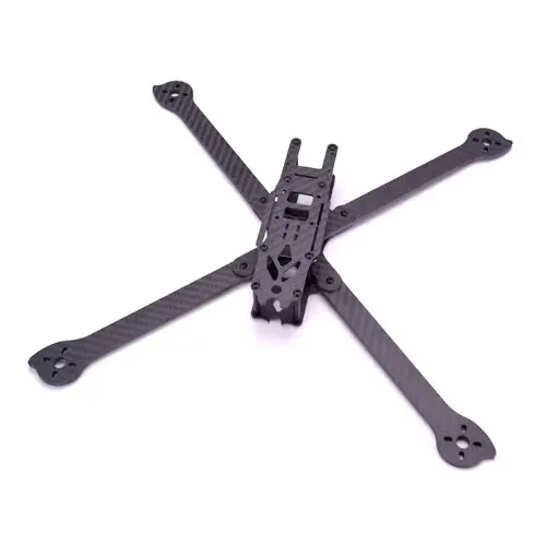
5-inch True-X or Deadcat frame such as Mark5, Apex 5 or TBS Source One V5. Check stack spacing and camera room.
FC and ESC
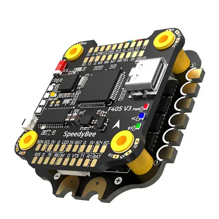
F405, F722 or H7 flight controller with a 50-60A 4-in-1 ESC that supports 6S and has current headroom.
Motors
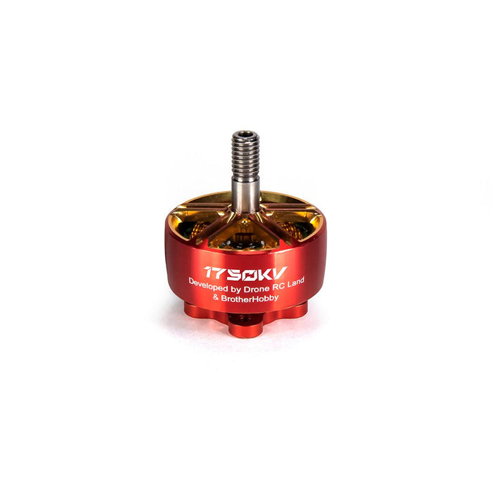
Four matching 2207 or 2306 motors around 1750-1950KV for 6S. Choose with the exact propeller in mind.
Radio and video
ELRS 2.4GHz such as RadioMaster RP1. Use an analog camera and 800mW+ VTX, or DJI O3, Walksnail or HDZero.
Battery
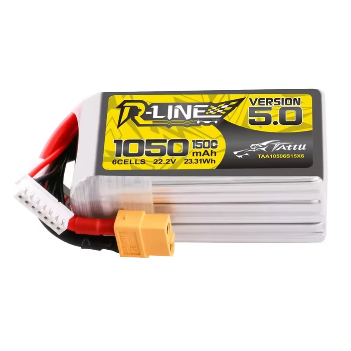
6S LiPo around 1100-1400mAh with a suitable C rating, XT60 and a secure strap.
Props
Tri-blade 5-inch props such as HQProp 5x4.3x3 or Gemfan 51466. Check CW and CCW orientation before fitting.
2. Tools and consumables
Prepare a soldering station around 380-400C, 60/40 solder with flux, M2/M3 hex drivers, cutters, tweezers, heat shrink, silicone wire, blue threadlocker and a smoke stopper.
3. Step 1: frame and motors
- Build the bottom plate, arms and top plate without cracking the carbon.
- Use a small amount of blue threadlocker on metal screws only.
- Install four matching motors and route the wires toward the center without tension.
- Critical: check screw length. A screw touching copper windings can short the motor and damage the ESC.
4. Step 2: ESC and power
- Install the ESC soft mounts on the center stack.
- Solder the 12/14 AWG XT60 power lead to VBAT and GND.
- Add a low-ESR capacitor, such as 35V 1000uF, directly to the ESC power pads with correct polarity.
- Trim and solder the three motor wires to each ESC motor output. Direction can be changed in software later.
5. Step 3: FC, ELRS and video
Mount the FC above the ESC using a harness or soft connectors. Confirm the exact board pinout before soldering.
Connect analog camera and VTX according to the FC VOUT/VIN diagram. Digital systems may need their own cable, power rail and MSP/UART setup.
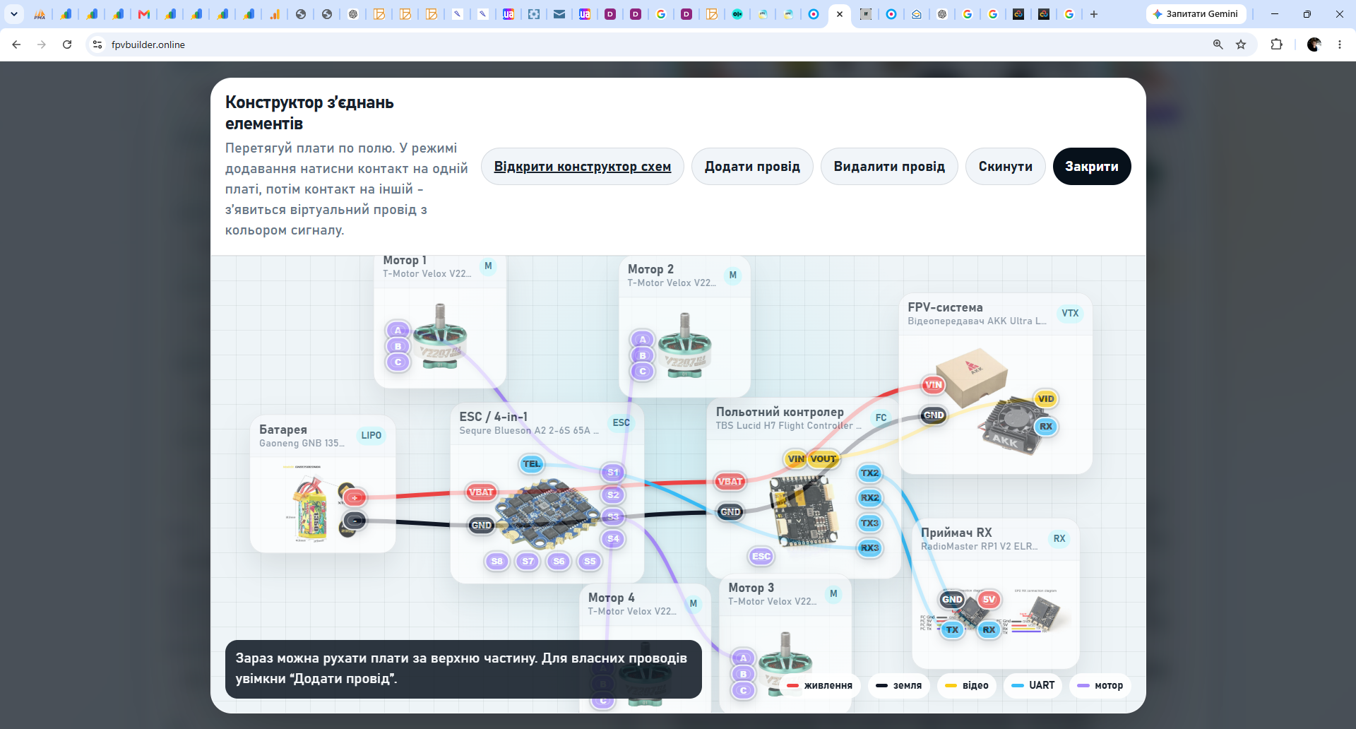
6. First power-up and Betaflight
- Use a multimeter to check XT60 and the absence of a short between positive and negative.
- Connect the 6S battery through a smoke stopper. Disconnect immediately if it limits current or signals a fault.
- In Ports, enable Serial RX for the receiver UART and SmartAudio, Tramp or MSP for VTX when supported.
- In Receiver, select CRSF for ELRS, verify channel movement and assign ARM.
- In Motors, check order and direction without props. Props Out is common, but Props In also works.
- Enable Bidirectional DShot for RPM filtering when the ESC and firmware support it.
7. Final pre-flight checklist
- Failsafe has been tested without props.
- The battery is secured by two straps and an anti-slip pad.
- Props are installed only at the flight location after all checks.
- The raised blade face points up and M5 nuts are tight.
- Motors have no play, debris or abnormal heat.
- The first flight is in a legal, open area away from people and obstacles.